Nuus
Uit wat bestaan 'n turbinevloeimeter?
'n Turbinevloeimeter is 'n tipe snelheidsvloeimeter, ook bekend as 'n lemvisvloeimeter. Dit is gebaseer op die beginsel van behoud van hoekmomentum.
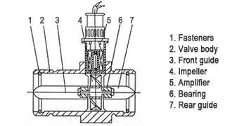
Die struktuur van 'n turbinevloeimeter word in die onderstaande figuur getoon. Wanneer vloeistof deur 'n pyplyn beweeg, slaan dit teen die turbineblaaie en veroorsaak dat die turbine draai. Die rotasiespoed van die turbine wissel volgens die vloeitempo. Die vloeitempo word bereken aan die hand van die turbine se rotasiespoed en word getel en op 'n sekondêre instrument aangedui. Hierdie sein kan beide oombliklike en kumulatiewe vloei (of totale vloei) weerspieël. Dit kan ook omgeskakel word na 'n standaardsein vir afstandsoorplanting. Verder kan die pulsfrekwensie-sein wat deur die sensor uitgevoer word, onafhanklik gebruik word saam met 'n rekenaar, waardeur die vloeimeter vervang kan word met 'n vloeitoonbank om digtheid, temperatuur en druk te kompenseer, en om die vloeistof se volume- of massavloeitempo aan te dui. Dit is een van die meer volwasse en hoogs akkurate vloeimeters wat tans beskikbaar is.
Komponente
ʼN Turbinevloeimeter bestaan gewoonlik uit 'n regtifier, instrumentseksie, sensor en 'n voorversterker.
Die gelyksteller is 'n toestel wat in die pyplyn geïnstalleer is, stroomop van die vloeimeter, om verskeie nie-asimmetriese en pulserende vloeie, soos wirbelstorms en eksentrisiteit, te elimineer of te verminder. Die instrumentseksie verwys na die pypgedeelte wat die gelyksteller, reguit pypseksies stroomop en stroomaf, en die vloeimeter insluit.
Die sensor is 'n toestel wat die rotor se rotasie omskep in 'n elektriese sein. Die turbine en sy samestelling (insluitend die voor- en agterste rigingsrame, laers, behuisings en voorversterker) wat die vloeistofsnelheid in 'n turbinevloeimeter waarneem, word algemeen verwys na as turbinevloeisensore.
Die voorversterker versterk en vorm die sensor se elektriese sein om 'n uitsetsein te genereer. Die seinverwerwing en omskakelingsgedeelte van die uitsetsein word 'n sekondêre instrument of vertooninstrument genoem.